.很多产品暂未上架 更多产品请联系我们
.如产品型号与展示图片不一致,以型号为准。具体产品图片联系我们,我们会安排到仓库拍照确认
.我们在全球有16个共享仓库,所以有时需要几个小时才能给您准确答复,当然,我们会尽快回复您的疑虑
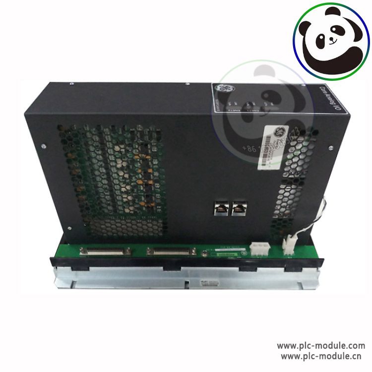
General Electric IS230PCAAH1A SPEEDTRONIC Turbine Control.The PCAA module has 120 Euro-style pluggable box terminals. A JGPA board, which mounts next to the module, provides 48 shield termination points (green) and twelve 24 V dc output terminals (orange) for 4-20 mA transmitters using Euro-style box terminals./Part Number: IS230STAIH2A Manufacturer: General Electric Series: Mark VIe Function: TERMINAL BOARD/General Electric Speedtronic Mark VIe IS230PCAAH1A Analog I/O Assembly Terminal Board is a part of gas turbine Control Systems /GE IS230PCAAH1A
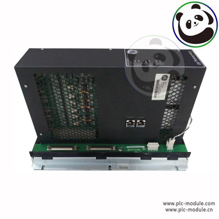
Functional Description
The module is suitable for use in simplex, dual, and TMR systems. A single TCAT terminal board distributes signal inputs to one, two, or three PCAA modules.
An adjacent JGPA board's shield ground and 24 V field power terminals supplement the terminals on PCAA and TCAT. Module includes a processor board that is shared by all Mark VIe distributed I/O boards, two application I/O boards, and a terminal board.
The entire module is regarded as the least replaceable unit, and no assistance is provided to diagnose or replace the individual boards that comprise the module.
The module is powered by a 28 V dc power connector and two RJ45 Ethernet connectors. On the module's edge, 120 Euro-style box terminals provide field device I/O. Power is supplied to a JGPA board via connector P4. The module is connected to TCAT via two 68-pin cables on connectors P1 and P2.
PCAA signals are divided into two groups. The TCAT terminal board routes signal inputs that can be fanned from a single input into a single, dual, or TMR PCAA module. Signals dedicated to a single PCAA module are wired to terminals. If the fanned inputs are not required, PCAA can be used without TCAT.
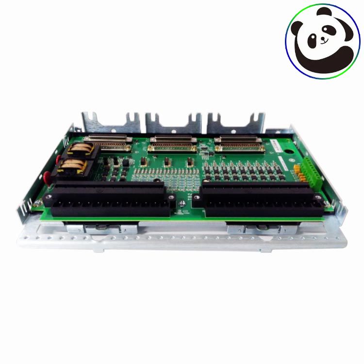
IS230PCAAH1A Installation
Firmly secure the PCAA module.
Connect the JGPA power connection to the PCAA's P4 connector.
Use two 68-pin cables on connectors P1 and P2 to connect the PCAA module to an optional associated TCAT terminal board. A network connection connects TCAT connectors. PR1 and PR2 connect to the R controller network, PS1 and PS2 connect to the S controller network, and PT1 and PT2 connect to the T controller network. To ensure proper cable grounding, fully seat the cable mounting screws, finger-tight only, into PCAA and TCAT. Failure to secure the cables may prevent Module from reading the electronic ID on TCAT and may degrade the quality of other signals.
Depending on the system configuration, connect one or two Ethernet cables. When only one IONet connection is used, the module can be used on either port. When using dual connections, it is common practice to connect ENET1 to the network associated with the R controller. The PCAA, on the other hand, is not concerned with Ethernet connections and will negotiate proper operation over either port. If TMR modules are present, the network connection should correspond to the TCAT connection. The PCAA module with R IONet connection, for example, should have cables that connect to the TCAT PR1 and PR2 connectors.
Verify that the JGPA shield wire terminals are properly grounded. In most cases, the JGPA shield ground terminals are electrically connected to the sheet metal on which the board is mounted. The mounting then serves as the terminals' ground path. In some applications, a shield ground that is independent of the mounting sheet metal must be defined. The JGPA is mounted in these applications using hardware that isolates the board from the sheet metal. It is critical to provide a suitable ground wire between one or more JGPA terminals and the required shield ground potential in these applications.
Connect the module to power via the P5 connector and inspect the power and Ethernet status indicator lights.
If necessary, use the ToolboxST application to configure the I/O pack.
Processor features
Two fully independent 10/100 Ethernet ports with connectors
Hardware watchdog timer and reset circuit
Internal temperature sensor
Status-indicating LEDs
Electronic ID and the ability to read IDs on other boards
Soft start/current limiter on the input power connector
Local power supplies, including sequencing and monitoring
Power Management
The 28 V input circuit includes power management. Soft start is provided by the management function to control current inrush during power application.
Following power application, the circuit implements a fast current limit function to prevent a power disturbance in the module from propagating back onto the 28 V power system.
The green PWR indicator will illuminate when power is present and functioning properly. If the current limit function is enabled, the indicator will be illuminated
 LAM 810-800082-043 PCBA VME BREAKOUT
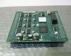 LAM 810-082745-003 Circuit Board PCBALONWORKS NODE
 LAM 810-082745-003 Circuit Board PCBALONWORKS NODE
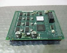 LAM 810-069751-114 PCBA NODE TYPE 411 CE
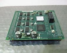 LAM 853-049542-173 ASSY TEMP CONT 24-CHANNEL
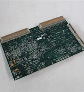 LAM 810-001489-016 PCBAROCKER VALVE INTFC BDI CE
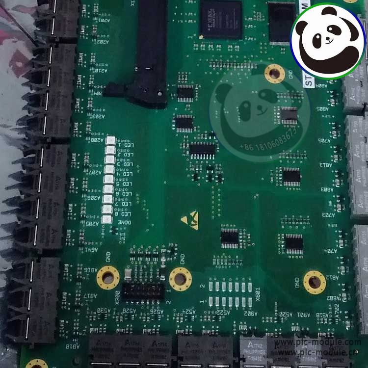 LAM 810-066590-004 PCBA.3-AXIS STPR DRIVER INTFC
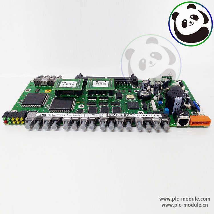 LAM 810-046015-010 PCBA VIOP III BOARD
 LAM 810-800081-022 PCB ASSY P2MB.V ME.ETCH
 LAM 810-102361-222 PCBA CHAMBER MUX
