
EMERSON 爱默生
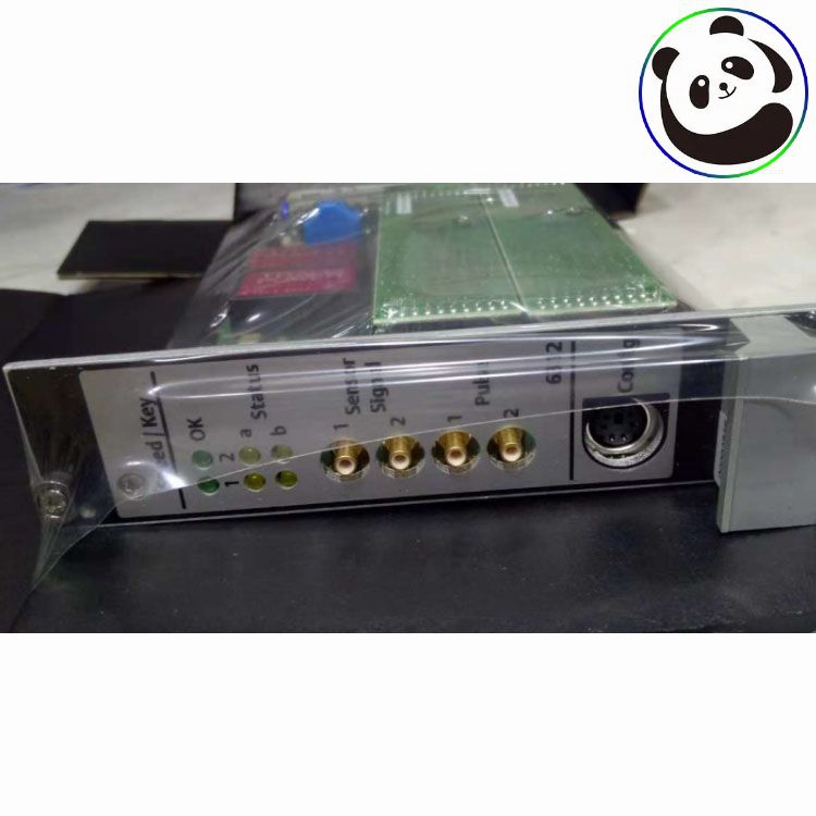
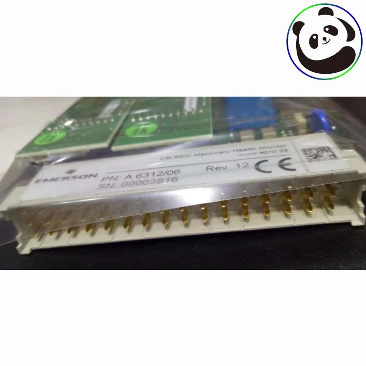
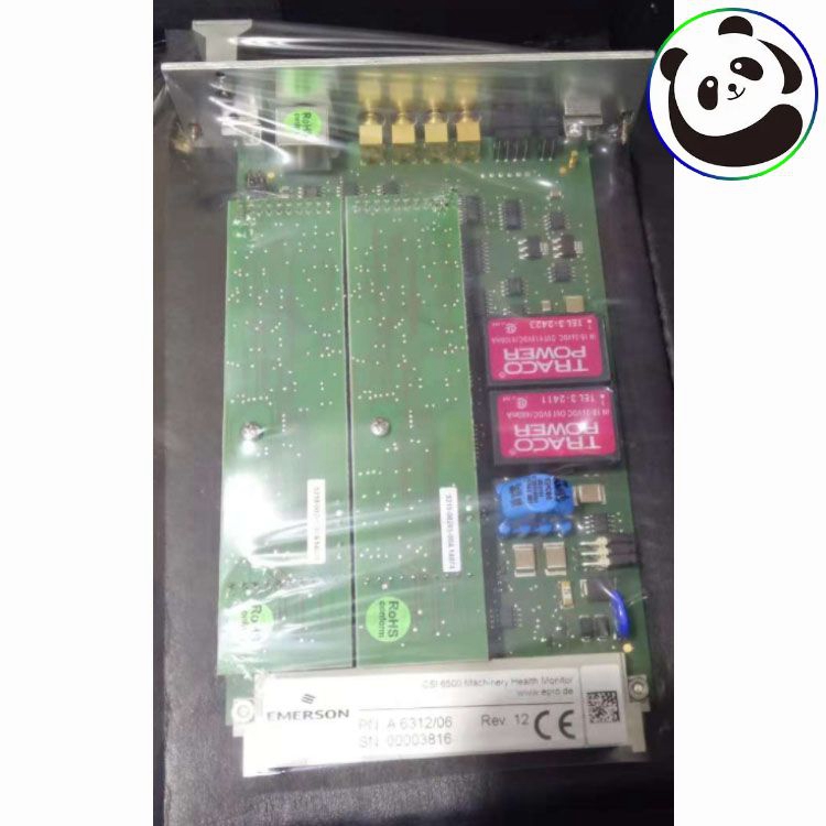
EMERSON A6312 9199-00024 Speed/Key Module (8HP)
.很多产品暂未上架 更多产品请联系我们
.如产品型号与展示图片不一致,以型号为准。具体产品图片联系我们,我们会安排到仓库拍照确认
.我们在全球有16个共享仓库,所以有时需要几个小时才能给您准确答复,当然,我们会尽快回复您的疑虑
EMERSON A6312 9199-00024 Speed/Key Module (8HP) A6312/06 A6312/08 Goods size : 9.5 x 6.75 x 2.5 cm; 13.6oz.In addition, damaged equipment is expensive and time-consuming to repair or replace. During transient and normal operation, the AMS 6300 SIS guards against overspeed conditions caused by sudden load loss and unexpected changes.


CSI 6500 Machinery Health Monitor A6312, Dual Channel Speed/ Key Monitor
The two−channel rotational speed monitor A6312 is a module of the A6000 machine monitoringsystem. The micro−processor controlled monitor is used in conjunction with two eddy currentmeasuring chains or hall−effect sensors (e.g. PR 9376) and in combination with triggeringwheels to measure and conditioning of shaft speeds and rotational reference marks(key−pulses).Both channels may be used separately used to measure:
•2 speeds from 2 shafts2 key−pulses from 2 shafts each with a triggermark (with phase relation)
•Both channels may also be used in combination with each other:to detect the direction of rotation of one shaft
•to detect a difference between two shaft speeds

A prepared 3U slot in a 19" rack, or other Intermas−compatible enclosure, is required formounting the A6312 monitor. The slot must be fitted with a 48−pin plug connector (DIN 41612,design F 48 M). The pin assignment is listed in the following table.
Jumper RS 485
RS 485 bus operation requires an electrical terminator on the first and last bus device.This is done with plug−in jumpers, that are on the controller board. The figure shows the positionof the jumpers

To activate the bus terminator and to place lines "A" and "B" on the references, plug the jumpersas shown in Fig. b). Fig. a) shows the jumper position for deactivated bus termination and openreferences (delivery status).
-
 LAM 810-800082-043 PCBA VME BREAKOUT
 -
 LAM 810-082745-003 Circuit Board PCBALONWORKS NODE
 -
LAM 810-082745-003 Circuit Board PCBALONWORKS NODE
-
 LAM 810-069751-114 PCBA NODE TYPE 411 CE
 -
 LAM 853-049542-173 ASSY TEMP CONT 24-CHANNEL
 -
 LAM 810-001489-016 PCBAROCKER VALVE INTFC BDI CE
 -
 LAM 810-066590-004 PCBA.3-AXIS STPR DRIVER INTFC
 -
 LAM 810-046015-010 PCBA VIOP III BOARD
 -
 LAM 810-800081-022 PCB ASSY P2MB.V ME.ETCH
 -
 LAM 810-102361-222 PCBA CHAMBER MUX