
EMERSON 爱默生
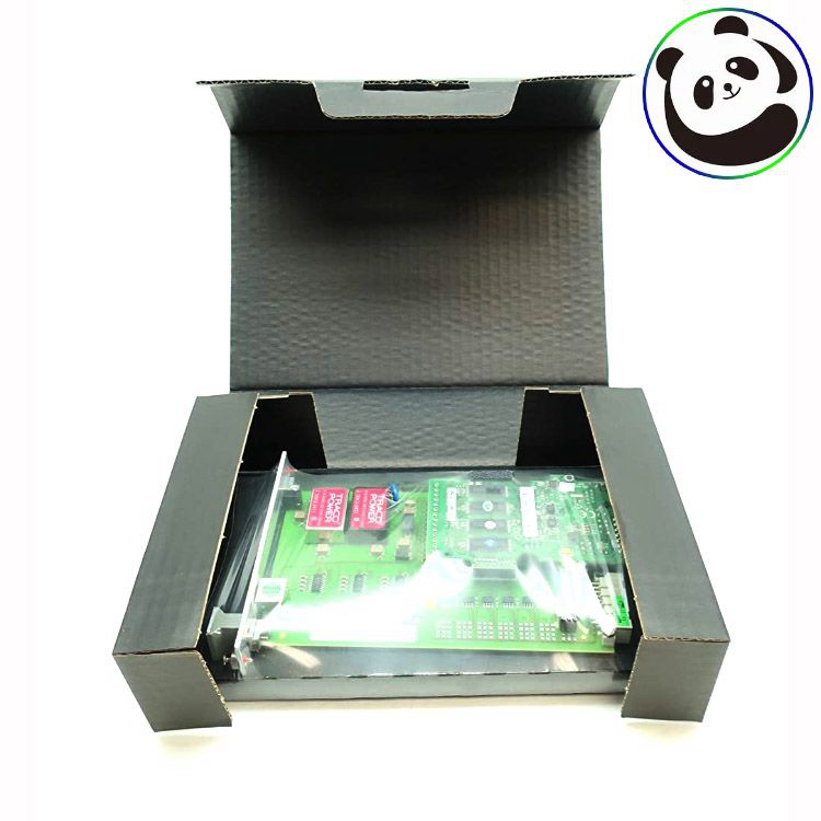
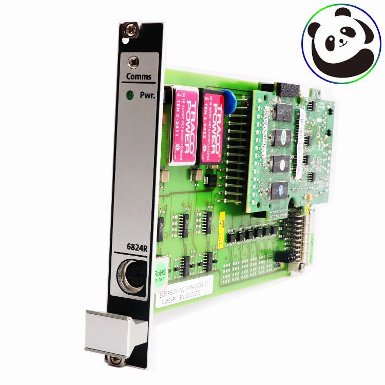
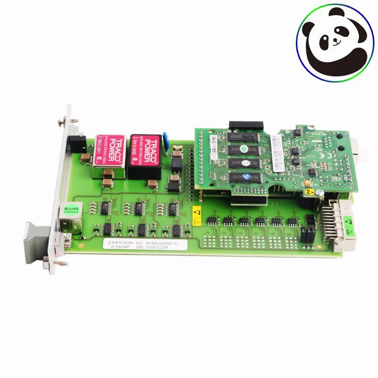
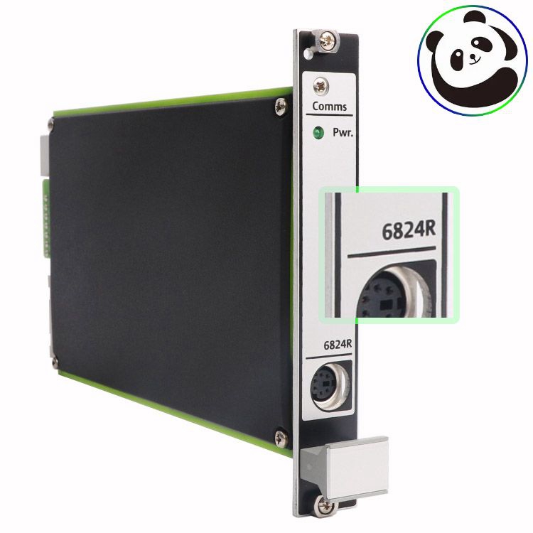
EMERSON A6824R 9199-00098-13 Modbus communication (4HP)
.很多产品暂未上架 更多产品请联系我们
.如产品型号与展示图片不一致,以型号为准。具体产品图片联系我们,我们会安排到仓库拍照确认
.我们在全球有16个共享仓库,所以有时需要几个小时才能给您准确答复,当然,我们会尽快回复您的疑虑
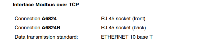
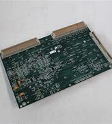
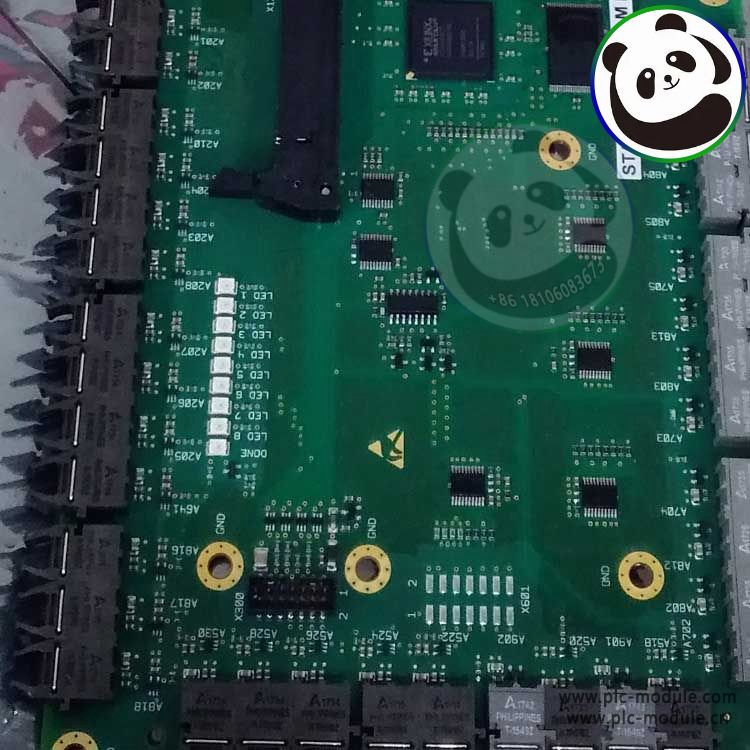
The A6824 / A6824R interface card is a component of the A6000 Machine Monitoring System.
The card serves the periodic recording of monitor data. The captured data are transmitted via
the interfaces Modbus RTU or Modbus over TCP.

The card has 6 RS 485 bus lines. Each of these lines can serve up to 8 A6000 monitors. By
means of the configuration, the monitors can be assigned to the bus lines of the interface card.

EMERSON A6824R 9199-00098-13 Modbus communication (4HP) .Implement a reliable and secure wireless infrastructure with Emerson Wireless Gateways
CSI 6500 Machinery Health Monitor
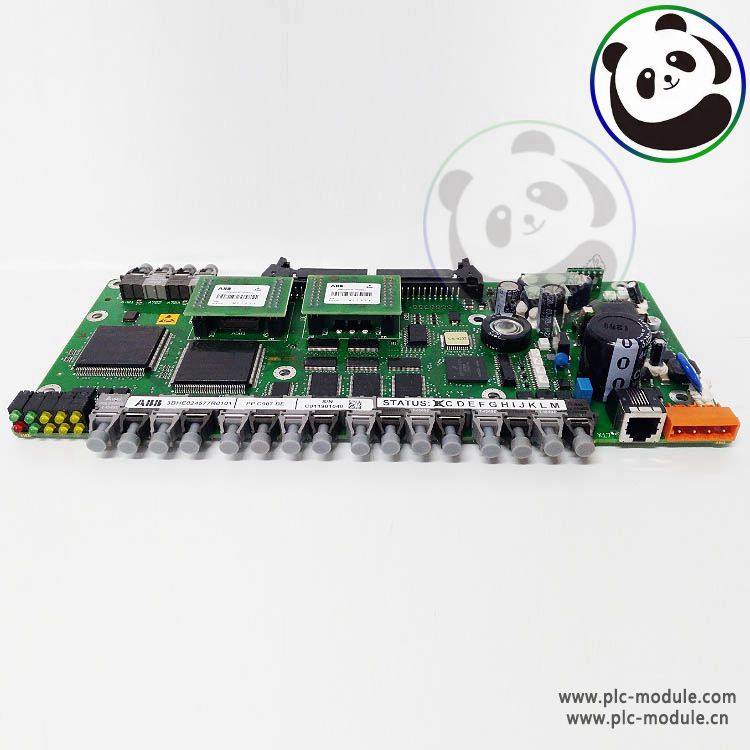
A6824/ A6824R, Gateway 6x RS485 to Modbus RTU and TCP/IP
")
For secure use of the monitor, observe the direction for use “Interface card A6824 / A6824R” (order number: 6110−90090). You can find this direction on the configuration software CD as pdf−data file. Amongst others, it contains useful informations for configuration and use of the A6824 / A6824R.
To ensure the safe operation of the monitor and to permit setting of all functions, it is indispensable to use only the latest version of configuration software (version 2.08 or newer) and operating manual.
The use of old operating manuals or configuration programs out of date may lead to malfunctions or limitations of the measuring functions.
Installation and Mounting
A prepared 3U slot in a 19” rack, or other Intermas−compatible enclosure, is required for mounting the A6824 / A6824R gateway.
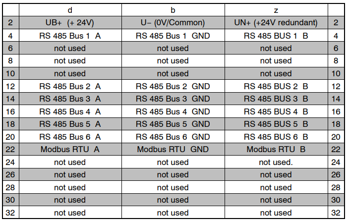
For use of the A6824R the slot must be fitted with a 30−pin plug connector (DIN 41612/IEC60603 design C/3). The pin assignment is listed in the following table.
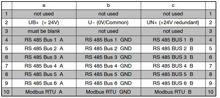
For use of the A6824 the slot must be fitted with a 48−pin plug connector (DIN 41612, design
F 48 M). The pin assignment is listed in the following table.
RS485
For faultless operation of an RS 485 bus, electrical terminations at the first and last device of the bus are required. This means that a 120 Ohm resistor must be installed between lines “A”and “B” next to the A6824 / A6824R interface converter and at the physically last device on the bus. Additionally, at the first or last device of the bus, the line “A” must be connected to +5V via a pull−up resistor and the line “B” to ground via a pull−down resistor.
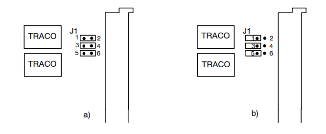
With use of the A6824 this can be done with plug−in jumpers, on the gateway−card. The figure shows the position of the jumpers for the 6 RS 485 bus lines.

To activate the bus terminator and to place the lines “A” and “B” on the references, plug the jumpers as shown in Fig. a). Fig. b) shows the jumper position for deactivated bus termination and open references.
• Jumper 1−2 closed: Line “B” of the bus is connected to ground via a pull−down resistor
• Jumper 3−4 closed: 120 Ohm resistance between “A” and “B”
• Jumper 5−6 closed: Line “A” of the bus connected to +5 V via pull−up resistor
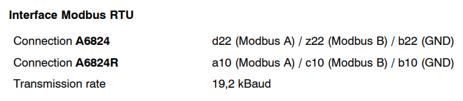
Modbus RTU Interface
The Modbus RTU protocol is output via an additional RS 485 interface. In the following figures,the jumpers for the Modbus RTU interface is marked with a white frame.


A6824
Installation
1. Check the slot wiring prior to installing the monitor.
2. Push the gateway A6824 / A6824R into the prepared slot and press it with light pressure
into the plug connector.
3. Hand tighten the two anchoring screws on the front panel to secure the gateway.

-
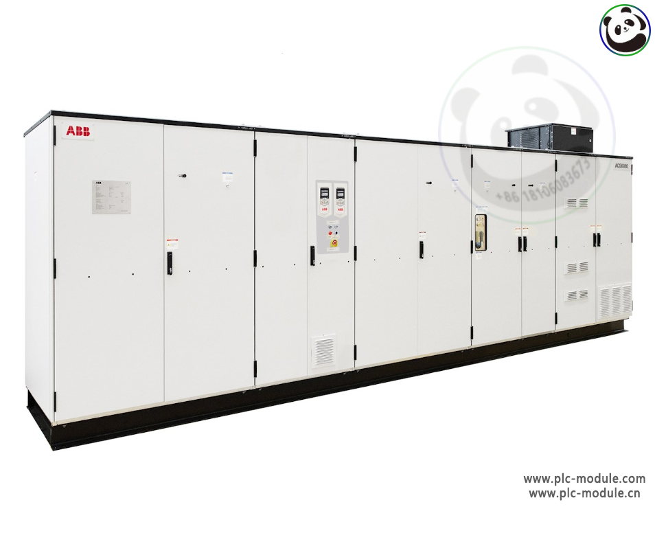 ABB ACS6080 中压驱动器 用于高性能电机控制
 -
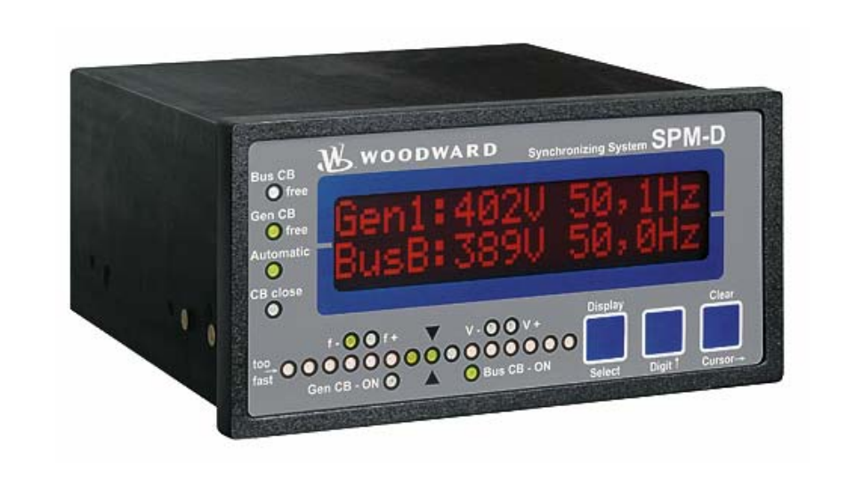 Woodward 伍德沃德 SPM-D11 系列 PDF
 -
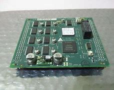
 LAM 810-800082-043 PCBA VME BREAKOUT
 -
 LAM 810-082745-003 Circuit Board PCBALONWORKS NODE
 -
LAM 810-082745-003 Circuit Board PCBALONWORKS NODE
-
 LAM 810-069751-114 PCBA NODE TYPE 411 CE
 -
 LAM 853-049542-173 ASSY TEMP CONT 24-CHANNEL
 -
 LAM 810-001489-016 PCBAROCKER VALVE INTFC BDI CE
 -
 LAM 810-066590-004 PCBA.3-AXIS STPR DRIVER INTFC
 -
 LAM 810-046015-010 PCBA VIOP III BOARD